
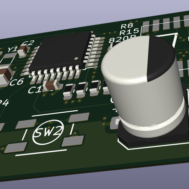
This is from a module I’m using and I don’t understand this part of it. https://files.waveshare.com/upload/3/3c/RP2040-Touch-LCD-1.28.pdf
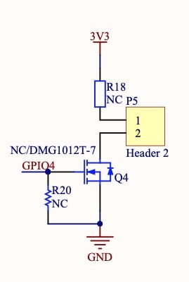
It looks like an n channel mosfet connecting the negative pin of the header to ground, with a resistor to keep the gate low (and consequentially keeping the mosfet on) until pulled high by gpio 4
with a resistor to keep the gate low
The resistor is 'not connected". That means its resistance is infinity, as there’s no real connection there.
It’s not connected but this is a very common circuit for driving some load efficiently that the gpio can’t handle for it self. The two pins probably go to some load like a LED, motor, or relay that the gpio can’t power on it’s on. When the transistor is off current will be almost zero so no power loss. When the transistor is on it’s resistance is close to zero using all the power in the unknown load and the resistor. The resistor is probably there for current limiting in case the pins are shorted.
Small MOSFETs have like single-digit nano-coulombs of charge. I don’t know what MOSFET this is, but lets take a jellybean 2N7000 for instance.
https://www.onsemi.com/pdf/datasheet/nds7002a-d.pdf

You can see that after 1 nano-coulomb the gate is charged and fully active. That means that even a 1uA GPIO pin can charge the 2N7000’s gate in just 1-milisecond (assuming it can reach the 5V needed to charge this old, crappy MOSFET). But yeah, the ridiculously low currents needed to drive MOSFETs are the reason why they’re so popular in electronic circuits.
You almost never need a resistor in practice. In fact, I’ve probably put more resistors in series with a MOSFET (slowing it down, to minimize noise / switching speeds).
Larger, so called “Power MOSFETs” have significant gate-charges, so you usually use a 2N7000 (or maybe even a dedicated MOSFET-driver chip) to drive those. But logic-level? Even the cheapest jellybeans? Tiny gate-charge, easy to use, very simple circuits. Don’t need a resistor at all.
Are you confusing a MOSFET (which is a voltage-controlled device) with a BJT? BJTs are current-controlled, and therefore need higher-amounts of current to drive well… higher currents. A Beta of 100 is reasonably common in the BJT world, and that’s just not enough for a typical GPIO to push a 5Amp motor or something. (ex: need 50mA and Beta 100 for BJT to drive 5Amp through a BJT).
I should have been clear about which resistor. I was talking about R18 as current limiter to the presumed load on the header. That way if the header gets shorted or the load has too high a draw at 3V3 you don’t blow the transistor.
R20 is probably a weak pull down resistor to keep the transistor off until the microcontroller comes online.
As far as the transistor I was thinking it was probably a 2N7000. That’s my goto in this kind of circuit.
Depending on the spefic microcontroller the pins can default to a very week high even when off. Enough to activate a 2N7000. I’ve had motors briefly engage using a PIC and a 2N7000 when the system is turned on without a pull down resistor.
deleted by creator
That’s a MOSFET, I always get confused if its n-mos or p-mos. Based on context, it looks like an nmos to me, enhancement mode.
MOSFETs are a voltage-controlled resistor. When GPIO4 is below the “threshold voltage”, the other two pins have a resistance of roughly 1-Gigaohm or so (basically disconnected). When GPIO4 is above the “threshold voltage”, things get very complex so lets… ignore the threshold region.
But once voltage gets “high enough”, then the resistance between 2-and-ground will drop to ~5 ohms to 0.05ohms, depending on the model of MOSFET. (The more expensive the MOSFET, the lower the resistance gets).
The diode is called the “body diode”, its innate to MOSFET construction. Its not a real diode you place, but instead just how MOSFETs work (MOSFETs are built on top of P-N doped junctions, so the Drain-pin and Source-pin have an effective diode across them)
In some cases, the Gate (aka: GPIO4 in this picture) has a voltage-protection circuit on it. That pin is famously sensitive to static electricity. If you ever put static-electricity on there (ex: walk across a carpet while holding onto that pin), the MOSFET can be damaged and could very well not function anymore. But many MOSFETs do not have any voltage-protection at all, so be careful.
The three pins on the MOSFET by the way, are named “gate”, “drain” and “source”. You may have heard of “Vss” and “Vdd”, this means “Voltage at Source” and “Voltage at Drain”, because most chips are MOSFET based. BJTs have similar pin names: “base”, “emitter”, and “collector”, and you may have seen Vcc (aka: Voltage at the collector) before in various notes when those devices are made out of BJTs internally.